Final Year (B.Tech) Project 2019-20
| Group Number | Year | Name of Students | Project / Model Title | Guide Name |
| Group-1 | 4th | VIJENDRA KUMAR,PAPPU VERMA,RAVI KANAUJIYA,AMEET KUMAR, SANDEEP YADAV,ASHISH YADAV,ANSUL VERMA | Fesibility of private e vehicle in india: challenges and opportunities. | Mr. Ravi Pratap |
| Group-2 | 4th | SUNIL KUMAR,ABHISHEK,ANUP KUMAR UPADHAYAY,AMIT KUMAR, RAVINDRA PRATAP SINGH,VEERBHAN SINGH | STUDY ON HYPER LOOP TECHNOLOGY | Mr. ADITYA NIGAM |
| Group-3 | 4th | Vikas Gupta,PAPPU SINGH,PRIYANSHU MISHRA, RANANJAY SINGH,BRAJESH SINGH,AVINASH RANJAN, RAJ | Research on zirconium alloy | Ms. KOMAL |
| Group-4 | 4th | RAMIT KUMAR SINGH,VIKKY SONKAR, YOGESH RAJAK,ASHUTOSH, SUDHEER KUMAR PRAJAPTI,PREM KUMAR,MAYANK SINGH | Study and analysis of automatic Braking system. | Mr.AMIT PANDEY |
Fesibility of private e vehicle in india: challenges and opportunities.
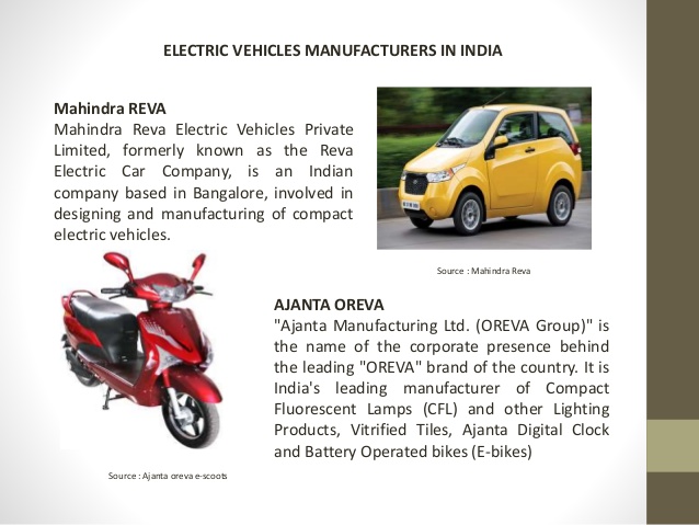
India is currently in the midst of a full-blown air pollution crisis. While pictures of entire cities engulfed in dense smog might garner national sympathy, albeit for a few weeks, a further inquisition into the numbers paints an even more harrowing picture. In India, the annual death toll from air pollution currently exceeds 1.6 million every year. Lung cancer is now the second largest cause of death after cardiovascular diseases, and it is increasingly affecting younger people as well as non-smokers. And while worldwide air pollution is ever on the rise, India has proved itself to be the epicentre of the crisis. The fact that 11 out of the 12 most polluted cities are located in India, as reported by the World Health Organization, is a testament to the scale of India’s precarious situation. In India, the transport sector emits an estimated 261 Tg of Carbon Dioxide, of which 94.5
per cent is contributed by road transport. The main pollutants discharged by vehicles consist of CO, unburnt HC, Pb, NO2 , SO2 and SPM from tailpipes. In total, by most estimates, vehicular pollution contributes to around 22.5 per cent of the total pollution. This pollution has concrete effects on the daily lives of citizens. A study by the International Council of Clean Transportation estimates that as much as two-thirds of all deaths from air pollution in India can be attributed to combustion engines. It is important to note that the amount of pollution caused by different groups of automobiles vary drastically. For instance, two wheelers and trucks account for about 70 per cent of all PM10 particles in the atmosphere. This can be mainly attributed to the laxity in regulations on these types of vehicles as compared to four wheelers. Around 70 per cent of three wheelers in India still use a two-stroke engine, which is highly polluting. Similarly, heavy duty trucks have been the slowest in reducing and improving their emission standards, as these standards are not uniform across the country. There is no simple answer to the problem of air pollution. A situation as bad as India’s must be addressed in a multi-faceted, holistic manner. One obvious solution would be to reduce the pollution from vehicular exhaust. In order to achieve this, the government has pushed for the electrification of vehicles in India. Electric vehicles (EVs) in the country have a tumultuous history. In the past, we have seen a flurry of proposals that have often been later redacted; for instance, in 2017 Transport Minister Nitin Gadkari famously announced that he intended for India to move to 100 per cent electric cars by 2030 to the shock of auto manufacturers in the nation. These plans were later diluted, from a 100 per cent electric future to a mere 30 per cent.
STUDY ON HYPER LOOP TECHNOLOGY
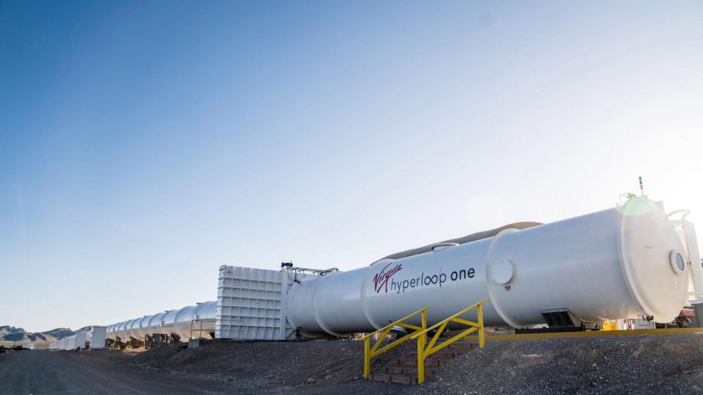
A Hyperloop is a proposed mode of passenger and freight transportation, first used to describe an open-source vactrain design released by a joint team from Tesla and SpaceX Hyperloop is a sealed tube or system of tubes with low air pressure through which a pod may travel substantially free of air resistance or friction The Hyperloop could convey people or objects at airline or hypersonic speeds while being very energy efficient This would drastically reduce travel times versus trains as well as planes[2] over distances of under approximately 1,500 kilometres (930 miles) Elon Musk first publicly mentioned the Hyperloop in 2012.[4] His initial concept incorporated reduced-pressure tubes in which pressurized capsules ride on air bearings driven by linear induction motors and axial compressors The Hyperloop Alpha concept was first published in August 2013, proposing and examining a route running from the Los Angeles region to the San Francisco Bay Area roughly following the Interstate corridor. The Hyperloop Genesis paper conceived of a hyperloop system that would propel passengers along the 350-mile (560 km) route at a speed of 760 mph (1,200 km/h), allowing for a travel time of 35 minutes, which is considerably faster than current rail or air travel times. Preliminary cost estimates for this LA–SF suggested route were included in the white paper—US$6 billion for a passenger-only version, and US$7.5 billion for a somewhat larger-diameter version transporting passengers and vehicles (Transportation analysts had doubts that the system could be constructed on that budget. Some analysts claimed that the Hyperloop would be several billion dollars overbudget, taking into consideration construction, development, and operation costs.The Hyperloop concept has been explicitly “open-sourced” by Musk and SpaceX, and others have been encouraged to take the ideas and further develop them. To that end, a few companies have been formed, and several interdisciplinary student-led teams are working to advance the technology SpaceX built an approximately 1-mile-long (1.6 km) subscale track for its pod design competition at its headquarters in Hawthorne California”We have just named the DP World – Virgin Hyperloop One consortium as the original project proponent for the Mumbai-Pune hyperloop project and [are] preparing to start the public procurement process,” he continued. “Maharashtra and India is at the forefront of hyperloop infrastructure building now and this is a moment of pride for our people.
RESEARCH ON ZIRCONIUM ALLOY
Zirconium alloys are solid solutions of zirconium or other metals, a common subgroup having the trade mark Zircaloy. Zirconium has very low absorption cross-section of thermal neutrons, high hardness, ductility and corrosion resistance. One of the main uses of zirconium alloys is in nuclear technology, as cladding of fuel rods in nuclear reactors, especially water reactor. A typical composition of nuclear-grade zirconium alloys is more than 95 weight percent zirconium and less than 2% of tin, niobium, iron, chromium, nickel and other metals, which are added to improve mechanical properties and corrosion resistance.
The water cooling of reactor zirconium alloys elevates requirement for their resistance to oxidation-related nodular corrosion. Furthermore, oxidative reaction of zirconium with water releases hydrogen gas, which partly diffuses into the alloy and forms zirconium hydrides. The hydrides are less dense and are weaker mechanically than the alloy; their formation results in blistering and cracking of the cladding – a phenomenon known as hydrogen embrittlement.
Production and properties
Commercial non-nuclear grade zirconium typically contains 1–5% of hafnium, whose neutron absorption cross-section is 600 times that of zirconium. Hafnium must therefore be almost entirely removed (reduced to < 0.02% of the alloy) for reactor applications.
Nuclear-grade zirconium alloys contain more than 95% Zr, and therefore most of their properties are similar to those of pure zirconium. The absorption cross section for thermal neutrons is 0.18 barn for zirconium, which is much lower than that for such common metals as iron (2.4 barn) and nickel (4.5 barn) The composition and the main applications of common reactor-grade alloys are summarized below. These alloys contain less than 0.3% of iron and chromium and 0.1–0.14% oxygen.
| Alloy | Sn, % | Nb, % | Vendor (country) | Component | Reactor type |
| Zircaloy 2 | 1.2–1.7 | – | All vendors | Cladding, structural components | BWR, CANDU |
| Zircaloy 4 | 1.2–1.7 | – | All vendors | Cladding, structural components | BWR, PWR, CANDU |
| ZIRLO | 0.7–1 | 1 | Westinghouse | Cladding | BWR, PWR |
| Zr Sponge | – | – | Japan and Russia | Cladding | BWR |
| ZrSn | 0.25 | – | Westinghouse | Cladding | BWR |
| Zr2.5Nb | – | 2.4–2.8 | Fabrica de Aleaciones Especiales(FAE)(Argentina) | Pressure tube | CANDU |
| E110 | – | 0.9–1.1 | Russia | Cladding | VVER |
| E125 | – | 2.5 | Russia | Pressure tube | RBMK |
| E635 | 0.8–1.3 | 0.8–1 | Russia | Structural components | VVER |
| M5 | – | 0.8–1.2 | Areva | Cladding, structural components | PWR |
Applications
This Russian shot “glass” is made of zirconium alloy.
Zirconium alloys are corrosion resistant and biocompatible, and therefore can be used for body implants. In one particular application, a Zr-2.5Nb alloy is formed into a knee or hip implant and then oxidized to produce a hard ceramic surface for use in bearing against a polyethylene component. This oxidized zirconium alloy material provides the beneficial surface properties of a ceramic (reduced friction and increased abrasion resistance), while retaining the beneficial bulk properties of the underlying metal (manufacturability, fracture toughness, and ductility), providing a good solution for these medical implant applications.
Reduction of zirconium demand in Russia due to nuclear demilitarization after the end of the cold war resulted in the exotic production of household zirconium items such as the vodka shot glass shown in the picture.
AUTOMATIC BRAKING SYSTEM
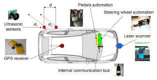
Braking is basically a mechanical action applied for slowing down of vehicles or even making the vehicle coming to halt depending upon the circumstances.
A.NEED FOR BRAKING SYSTEM
When a safety factor of a vehicle is considered a primary factor that flashes in mind is its brakes or braking system.So a braking system is such a vital component that is necessarily required when a vehicle is considered. It reduces the kinetic energy of the vehicle in conditions when a vehicle has to slow down or also it has to be stopped.Thus making sure the vehicle and the passengers inside it are safe. Thus a braking system is always needed to ensure the safety of the drivers and passengers uncountable valued lives.
B.PROBLEM STATEMENT
The conventional friction brake system is composed of the following basic components: the “master cylinder”which is located under the hood is directly connected to the brake pedal, and converts the drivers’ foot pressure into hydraulic pressure. Steel “brake hoses” connect the master cylinder to the “slave cylinders” located at each wheel. Brake fluid, specially designed to work in extreme temperature conditions, fills the system. “Shoes” or “pads” arepushed by the slave cylinders to contact the “drums” or “rotors,” thus causing drag, which slows the car. Two major kinds of friction brakes are disc brakes and drum brakes. Disc brakes use a clamping action to produce friction between the “rotor” and the “pads” mounted in the“caliper” attached to the suspension members. Disc brakes work using the same basic principle as the brakes on a
bicycle: as the caliper pinches the wheel with pads on both sides, it slows the vehicle (Limpert 1992).Drum brakes consist of a heavy flat-topped cylinder, which is sandwiched between the wheel rim and the wheel hub. The inside surface of the drum is acted upon by the linings of the brake shoes. When the brakes are applied, the brake shoes are forced into contact with the inside surface of the brake drum to slow the rotation of the wheels (Limpert1992). Air brakes use standard hydraulic brake system components such as braking lines, wheel cylinders and a slave cylinder similar to a master cylinder to transmit the air-pressure-produced braking energy to the wheel brakes. Air brakes are used frequently when greater braking capacity is required.All the above mentioned convectional brakes have two chief problems one is the wear and tear and other is
unnecessary excessive temperature in the service is attained.
Excessive heating of brakes can result in fade .it causes temporary changes in the friction as they get hotter. Normally efficiency is regained when they cool again Brake pads and linings also wear away faster at higher temperatures.
C.APPROACH TO THE SOLUTION
As seen in the above-mentioned problem with the convectional brakes the problem is arises due to the friction between two or more rubbing parts. Hence electromagnetic brakes can be used as a replacement which is totally frictionless. And due to which there is no question of wear and tear of parts and unnecessary temperature issues as there is no friction in this braking system.This results in stable efficiency of the braking system for a longer service span. In addition, it results in longer life span of the braking system without any wear and tear. This also gives the answer for the replacement of cooling system. Therefore, the electromagnetic brakes give the answers for the questions that arise in the convectional braking
systems.Properties of the material used for brake pads and linings, and the brakes becomes less efficient.
Final Year (Diploma) Project 2019-20
| Group Number | Year | Name of Students | Project / Model Title | Faculty |
| Group-1 | 3rd | ABHISHEK VERMA, AJAY SINGH,AJIT KUMAR,ANIL DIWAKAR,YOGENDRA SAHU ,Md. INJMAM,AMAN SINGH | Cost benifit analysis for panki thermal power plant. | RAVI PRATAP |
| Group-2 | 3rd | ASHISH KUMAR, RAVINDRA RAJPOOT,AKASH RAJPOOT,SHARAD CHAURASIYA, SATYAM PAL,VISHAL KUMAR,MAHENDRA PRATAP | Automatic car Parking. | KOMAL |
| Group-3 | 3rd | SAURABH MAURYA, SHIVDEVMANI ,SHIVAM DUBEY,ATUL KUMAR,SAHIL KUMAR,NANHE CHAUHAN,RISHI KUMAR | STUDY AND ANALYSIS OF FAILURE OF TATA NANO | ASHUTOSH |
| Group-4 | 3rd | NIKHIL KUMAR,RAM NAYAN MAURYA,RISHABH SINGH,PUSHPENDRA SAGAR, GOVIND KUSHWAHA,BRIJMOHAN, SATYAM SINGH | Study of design of motorized wheel chair | AMIT PANDEY |
| Group-5 | 3rd | PRAKHAR PATHAK,SHATYAM SINGH,BRIJ BHUSHAN,ATIF KAMMAL,KARTIKEY SINGH,HIMANSHU SACHAN,UJJAWAL PANDEY | STUDY AND ANALYSIS OF ELECTRIC VEHICLE | ARVIND KUMAR |